Rigging Information

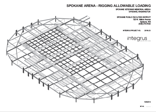
The Spokane Veterans Memorial Arena has been designed to accommodate significant loading from rigging assemblies. A rigging support grid has been established to carry a large variety of loading layouts. The rigging grid is located approximately at an elevation of 69 feet above the arena floor. The assembly is made up of 4 separate elements:

  • R1 Beams: Spanning in the north-south direction
  • R2 Beams: Spanning in the east-west direction
  • R3 Beams: Diagonal members on north and south edge of grid which cannot be used as direct support of applied rigging loads.
  • Main Roof Trusses: Supporting R1 and R2 beams which connect to bottom flange of trusses.

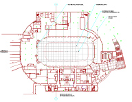
All members used in the rigging grid are structural steel wide flange (I-beams). Load capacities for these elements are shown on the sheets which follow. See sketch 1 for plan layout of the rigging support grid. See sketch 2 for examples of rigging load applications acting on the grid.

Beam Layouts

Click images to download detailed view:

Sketch 1 Sketch One

Sketch 2 Sketch Two

Sketch 3 Sketch Three

Sketch 4 Sketch Four

Sketch 5 Sketch Five

R1 Beam Capacity Layouts

Note 1: Loads may be applied in any direction.
Note 2: Capacity shown are total combined load that can be applied in given region for the given layout option.
Note 3: See sketch for requirements adjacent to video screen hoist beams.

A

B

C

D

E

Option 1

20,000 lbs. applied in any one region

Option 2

0 7,500 lbs. 7,500 lbs. 7,500 lbs. 0

Option 3

6,000 lbs. 6,000 lbs. 6,000 lbs. 6,000 lbs. 6,000 lbs.

Option 4

0 0 11,000 lbs. 11,000 lbs. 0

Option 5

0 11,000 lbs. 11,000 lbs. 0 0

Option 6

14,000 lbs. 0 14,000 lbs. 0 0

Option 7

0 0 14,000 lbs. 0 14,000 lbs.

Option 8

0 13,000 lbs. 0 13,000 lbs. 0

R2 Beam Capacity Layouts

Note 1: Loads may be applied in any direction.
Note 2: Capacity shown are total combined load that can be applied in given region for the given layout option. Loading from incoming rigging beams must also be included in combined load summation.
Note 3: See sketch for requirements adjacent to video screen hoist beams.

A

B

C

D

E

Option 1

30,000 lbs. applied in any one region

Option 2

0 8,500 lbs. 8,500 lbs. 8,500 lbs. 0

Option 3

7,000 lbs. 7,000 lbs. 7,000 lbs. 7,000 lbs. 7,000 lbs.

Option 4

0 0 13,000 lbs. 13,000 lbs. 0

Option 5

0 13,000 lbs. 13,000 lbs. 0 0

Option 6

16,000 lbs. 0 16,000 lbs. 0 0

Option 7

0 0 16,000 lbs. 0 16,000 lbs.

Option 8

0 14,000 lbs. 0 14,000 lbs. 0

Graphic Schematics

Seating Map Event Level Map Concourse
Standard Seating Map
(pdf)
Event Level Maps
(pdf - 3 pages)
Concourse Level Maps
(pdf - 3 pages)
     
Upper Level Press Level Catwalk
Upper Level
(pdf)
Press Level
(pdf)
Catwalk
(pdf)